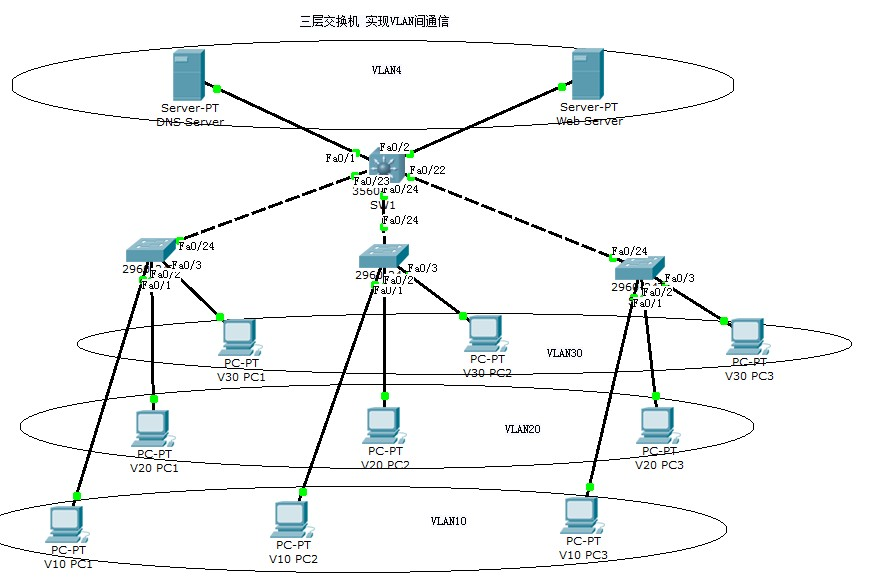
实际局域网划分VLAN后,每个VLAN是一个单独的广播域,所以在默认情况下,不同VLAN中的计算机无法通信。允许此类计算机之间通信的一种方法是VLAN间路由,它是使用三层设备(如三层交换或路由器)从一个VLAN向另一个VLAN转发流量的过程。
VLAN与网络中唯一的IP子网相关联,VLAN中的每个设备配置一个相同网段的IP地址,不同的VLAN使用不同网段的IP地址。这种子网VLAN关联简化了多VLAN环境中的路由处理。三层交换机属于三层设备,因此,它是实现VLAN间设备通信的良好选择。
为了使第三层交换机执行路由功能,交换机上的VLAN接口需配置合适的IP地址,该地址就是VLAN中主机的网关地址。
下面通过一个实例来看三层交换机如何实现VLAN间路由。
下图所示是一个校园网的网络拓扑,要求所有计算机能够通过域名 ncxyol.com 访问web服务器,并且不同VLAN间的计算机可以相互通信。

VLAN划分如下:
VLAN10:

PC1:192.168.1.1

PC2:192.168.1.2

PC3:192.168.1.3

默认网关:192.168.1.254

DNSserver:192.168.40.1

VLAN20:

PC1:192.168.2.1

PC2:192.168.2.2

PC3:192.168.2.3

默认网关:192.168.2.254

DNSserver:192.168.40.1

VLAN30:

PC1:192.168.3.1

PC2:192.168.3.2

PC3:192.168.3.3

默认网关:192.168.3.254

DNSserver:192.168.40.1

VLAN40:

DNS服务器:192.168.40.1

在DNS服务器上添加一A条记录即web服务器的域名解析:ncxyol.com  192.168.40.2

Web服务器:192.168.40.2

默认网关:192.168.40.254
交换机配置如下:
SW1(三层交换机)

en

config t

vtp mode server

vtp domain jxdy

vlan 10

name jxdy1

vlan 20

name jxdy2

vlan 30

name jxdy3

vlan 40

name jxdy4

int range f0/22 - 24

sw mode trunk

no sh

int range f0/1 - 2

swit mode acc

sw acc vlan 40

no shut

int vlan 10

ip add 192.168.1.254 255.255.255.0

no shut

int vlan 20

ip add 192.168.2.254 255.255.255.0

no shut

int vlan 30

ip add 192.168.3.254 255.255.255.0

no shut

int vlan 40

ip add 192.168.40.254 255.255.255.0

no shut

SW2

en

config t

vtp mode cli

vtp domain jxdy

int f0/24

swit mod trunk

no sh

exit

int f0/1

swit mode acc

swit acc vlan 10

no shut

int f0/2

swit mode acc

swit acc vlan 20

no shut

int f0/3

swit mode acc

swit acc vlan 30

no shut

SW3

en

config t

vtp mode cli

vtp domain jxdy

int f0/24

swit mod trunk

no sh

exit

int f0/1

swit mode acc

swit acc vlan 10

no shut

int f0/2

swit mode acc

swit acc vlan 20

no shut

int f0/3

swit mode acc

swit acc vlan 30

no shut

SW4

en

config t

vtp mode cli

vtp domain jxdy

int f0/24

swit mod trunk

no sh

exit

int f0/1

swit mode acc

swit acc vlan 10

no shut

int f0/2

swit mode acc

swit acc vlan 20

no shut

int f0/3

swit mode acc

swit acc vlan 30

no shut
按照如上方法配置成功以后,在SW1(三层交换机)上 show ip route 会发现四个直连路由:
Switch#show ip route

Codes: C - connected, S - static, I - IGRP, R - RIP, M - mobile, B - BGP

       D - EIGRP, EX - EIGRP external, O - OSPF, IA - OSPF inter area

       N1 - OSPF NSSA external type 1, N2 - OSPF NSSA external type 2

       E1 - OSPF external type 1, E2 - OSPF external type 2, E - EGP

       i - IS-IS, L1 - IS-IS level-1, L2 - IS-IS level-2, ia - IS-IS inter area

       * - candidate default, U - per-user static route, o - ODR

       P - periodic downloaded static route

Gateway of last resort is not set

C    192.168.1.0/24 is directly connected, Vlan10

C    192.168.2.0/24 is directly connected, Vlan20

C    192.168.3.0/24 is directly connected, Vlan30

C    192.168.40.0/24 is directly connected, Vlan40
配置就绪以后测试就会发现不同VLAN间可以通信了。
详细实验见附件: